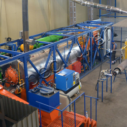
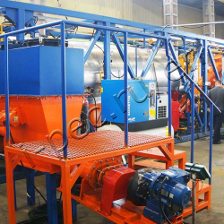
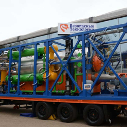
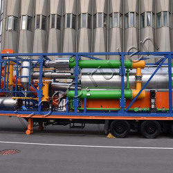
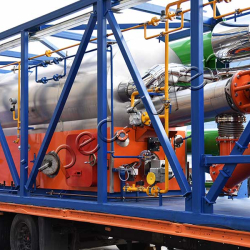
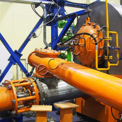
Continuous Thermal Decomposition Plant (TDP-2-200)
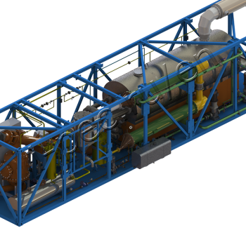
Technical characteristics
200 kg/h capacity
continuous operation batches per day
10 kWh power consumption
380 volt voltage
- oil sludge
- drilling sludge
- acid sludge
- coal, coal-tar
- used rubber and tires
- plastic masses
- used lubrication materials
- e-waste
-
The process is based on low-temperature pyrolysis, involving the use of heat to thermally decompose the feedstock in the condition of oxygen deficit. Marketable products are obtained as a result of the processing of raw materials.
Usage of the product derived from hydrocarbon (organic) materials:
- Boiler fuel =>
=> used for its intended purpose
=> used to obtain gasoline, diesel fuel fraction when additional equipment (distillation column) is supplied
- Dry residue is used for local, construction and reclamation needs
- Heat produced during the process (about 150 kWh) is used for the room heating
- Pyrolysis gas is used for the plant operation
Usage of the product derived from water-based materials:
- Distilled water =>
=> used for drilling mud preparation
=> used as process water when installing the system of additional purification
=> used as drinking water when installing the system of additional purification and mineralization
- Dry residue is used for local, construction and reclamation needs
- Heat of the process (about 150 kWh) is used for the room heating
ADVANTAGES OF TDP-2-200:
- continuous mode of processing
- low energy consumption – 10 KW
- simultaneous feeding of dry and liquid materials
- efficient maintenance of the heating chamber, lining and blast cover
- mobility
- built-in cooling system
- additional chiller
-
TDP-2-200 process description:
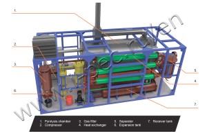
1. Raw material are fed to the pyrolysis chamber on continuous mode:
=> solid waste by screw conveyor;
=> liquid waste by pump.
2. Boiler fuel or diesel oil is self-fed to the burner from fuel tank.
3. Air is fed to the burner by compressor, which is switched to the pyrolysis gas after the process is stabilized.
4. Vapor-gas mixture from pyrolysis chamber comes to the condensation system through gas filter.
5. The further cooling is carried out in a heat exchanger.
6. Expansion tank compensate chilled water volume.
7. The cooled mix enters the separator where it split up on fractions:
=> pyrolysis oil is directed to the receiver tank;
=> pyrolysis gas is directed to the buster burners.
8. Solid residue is discharged by screw conveyor, cools in hopper and transported to the storage bin.

