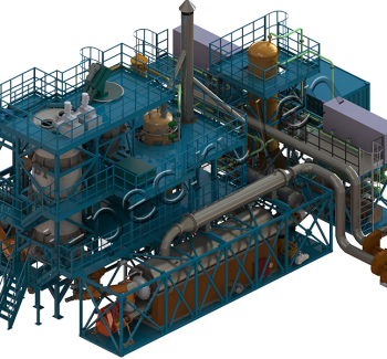
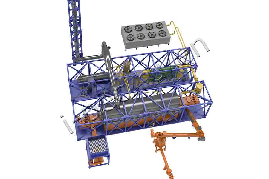
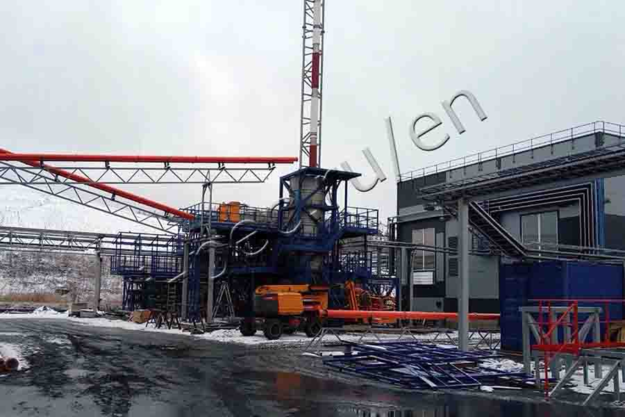
Continuous Thermal Decomposition Plant (TDP-2-2000)
Technical characteristics
2000 kg/h capacity
continuous operation batches per day
45 kWh power consumption
380 volt voltage
- oil sludge
- drilling sludge
- acid sludge
-
ADVANTAGES OF TDP-2-2000
- !! minimal air emissions
- unique continuous pyrolysis process for the conversion of hydrocarbon-based materials of any composition
- no feedstock pretreatment
- CAPACITY – up to 2000 kg/h
- mobility:
dimensions – TWO 40 ft’ containers (process equipment)
ONE 40 ft’ container – operator’s (additional unit)
- operators – 2 persons
ADDITIONAL FEATURES (OPTIONAL):
- Energy recovery. Thermal energy output capability.
- Autonomous power generation.*
Capstone MicroTurbine => pyrolysis gas electricity production
Electric energy output capability.
The amount of electricity generated is calculated in each case; depends on calorific value, type and volume of raw materials!
The option enables:
- reduce the burden on facility’s power supply during a peak period;
- provide electricity to facility / field / locality;
- create additional reserves of energy saving in case of emergencies;
- use process products (pyrolysis gas and oil) as an alternative energy source.
______________
* When two Capstone generators provided.
-
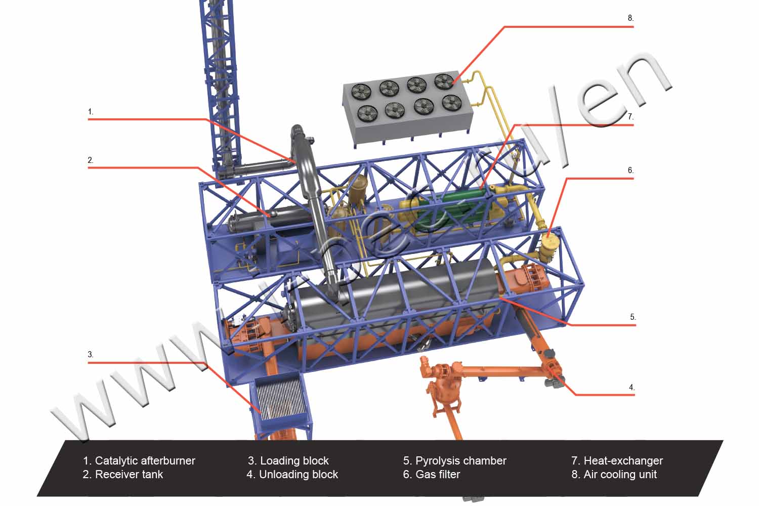
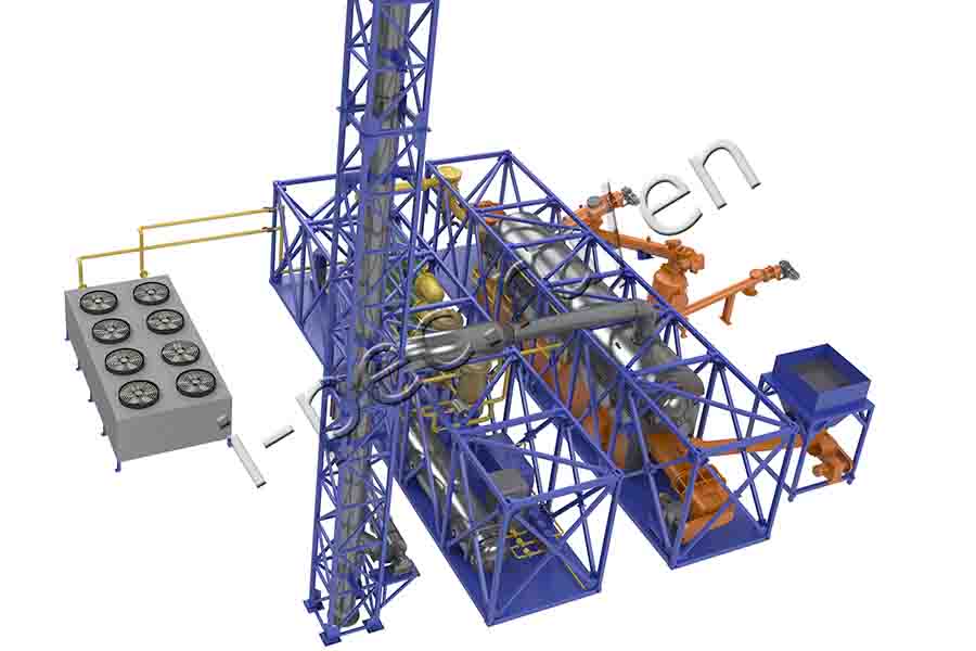
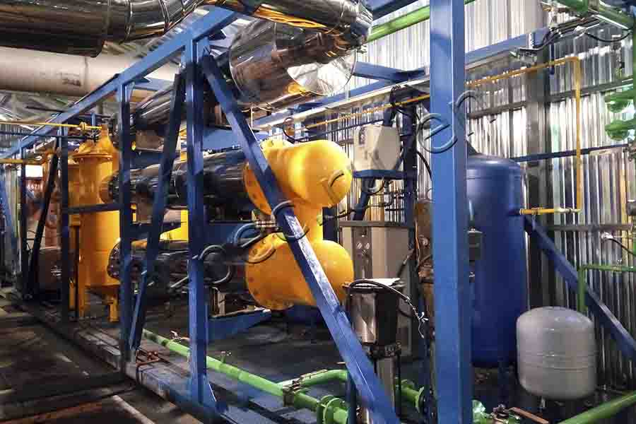
1. The raw material is continuously fed into the pyrolysis chamber:
=> Solid waste is fed by screw conveyor;
=> Liquid waste is fed from the receiver tank by pump.
2. Fuel is self-fed from fuel tank.
3. Air is fed to the burner by compressor while operating on diesel or boiler fuel. After process stabilizing the burner capacity is lowered and heating is carried out on pyrolysis gas.
4. Vapor-gas mix is directed through gas filter to condensate assembly.
5. Vapor-gas mix is cooled in the heat exchanger.
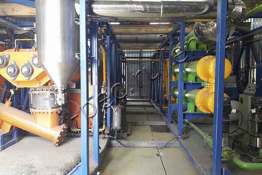
6. Water is cooled in air cooler unit.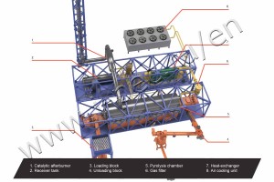 7. Vapor-gas mix then enters separator where it is separated to liquid and gas phases.
=> Pyrolysis liquid fuel is fed into the storage tank;
=> Pyrolysis gas after cleaning is fed to a burner;
=> The dry residue is fed by a screw conveyor. Then it is cooled in a hermetically sealed bunker and it is transported to storage hopper.
Autonomous power generation: pyrolysis gas/oil comes to the Capstone generators for the electricity production.


")


